Microbit LED blinkenlights
I found some old bits of electronics hiding in a box in storage the other day so I was reminded of my past electronics history but also inspired to make a couple of simple circuits that would work with the digital IO on the microbit.
LEDs
A lot of electronics work without an externally visible sign that anything is going on. An LED is one of the most simple electronic devices that does something that someone can actually see and appreciate that there is work happening. The standard circuit for an LED to work looks like this.
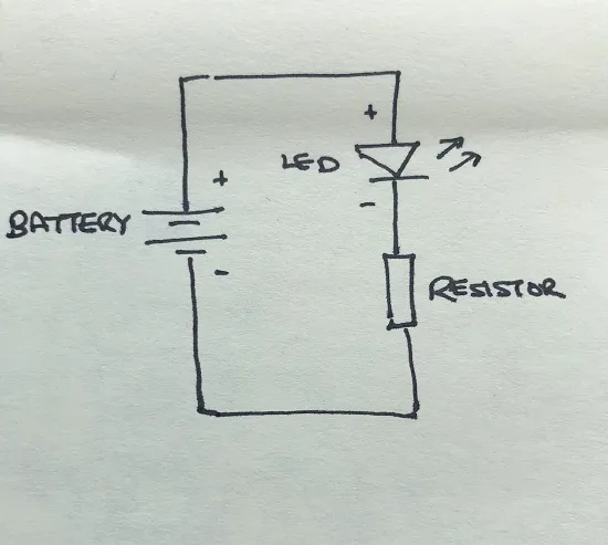
The battery provides the voltage, the LED will light up when current is flowing through it in the right direction and the resistor is there to make sure that the LED doesn't try to take up too much current and blow itself up.
LEDs have a long leg (positive) and a short leg (negative) that can be used when orienting them in a circuit. If the LED is soldered down, the legs are usually cut to the same length. Luckily, the body of the LED also has a flat side to it which also marks the negative end of the device.

If the LED is connected up the "wrong" way round, no current will flow and the light won't be lit but the circuit won't break.
Experimentation
Now that we have the basics straight, we need to think about how to do this with a microbit in control. A digital IO pin on the edge connector can be connected to our circuit in place of the top of the battery part of the circuit and the other end of the circuit attached to the GND pin on the edge connector.
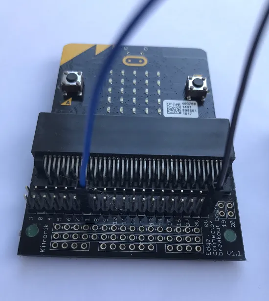
Here I have attached two wires to the edge connector, to pin 1 and to the gnd pin.
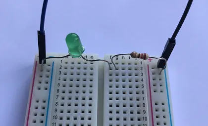
A "breadboard" is a sort of staging area for circuits to be constructed while being developed before the design is committed to a more permanent form, say as a printed circuit (PCB). In the picture below, I connected the wire from pin 1 to the left hand + column on the breadboard and the gnd wire to the right hand - column. In between we have the LED connected between the + and a slot in the middle of the breadboard. The resistor connects to that and to the - column to complete the circuit.
Code
from microbit import *

blink_delay = 500

def show_led(on):
    io_value = 1 if on else 0
    pin1.write_digital(io_value)
    pixel_value = 9 if on else 0
    display.set_pixel(2, 2, pixel_value)

while True:
    show_led(True)
    sleep(blink_delay)
    show_led(False)
    sleep(blink_delay)
As a debugging aid, I elected to wrap the digital IO functionality in a function so that I could blink the central LED on the internal display at the same time as I was turning on and off the output pin.
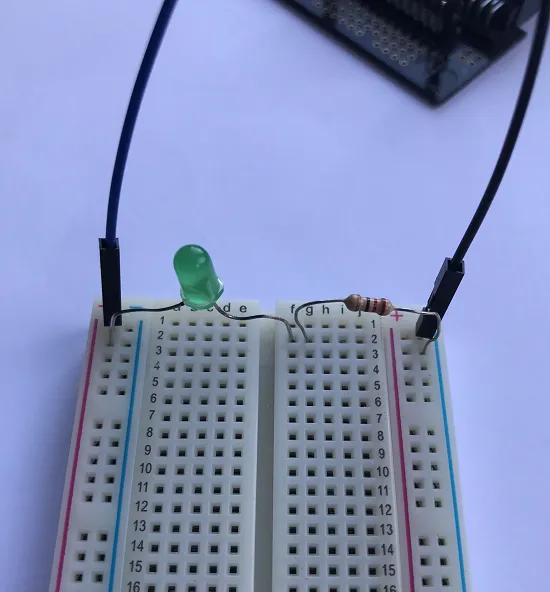
Here's the working circuit:
Now I have my wiring and breadboard and breakout edge connector to hand, I'll try to post some more electronics projects.
Traffic Lights
From one LED to a number of them is a matter of replicating what we have already done and assigning each LED to a different out. To take the traffic light example where we cycle between green, red, amber and back to green, each LED has to be assigned to a workable digital io pin (see here for reference) on a separate portion of the breadboard.
from microbit import *

light_delay = 1000

red = pin8
amber = pin12
green = pin16

on = 1
off = 0

while True:
    # Stop
    green.write_digital(off)
    amber.write_digital(off)
    red.write_digital(on)
    sleep(light_delay)
    # Get Ready
    amber.write_digital(on)
    sleep(light_delay)
    # Go
    red.write_digital(off)
    amber.write_digital(off)
    green.write_digital(on)
    sleep(light_delay)
    # Stop if safe
    green.write_digital(off)
    amber.write_digital(on)
    sleep(light_delay)